


EEE Department
Preventive Maintenance of Laboratory
- Preventive maintenance schedules are followed regularly to ensure the smooth and reliable functioning of all laboratory equipment as per occupancy chart (Lab time table).
- Electrical and electronic measuring instruments are inspected and calibrated periodically to ensure accurate measurements.
- Electrical connections, cables, switches, plugs, sockets, and earthing systems are inspected regularly for safe operation.
- Laboratory equipment and instruments are inspected periodically to identify faults before they lead to equipment failure or breakdown.
- Electrical machines, transformers, power electronic equipment, control systems, and other laboratory instruments are checked periodically for proper functioning.
- Machines and equipment are cleaned regularly to maintain proper working conditions and prevent dust accumulation and damage.
- Moving parts of electrical machines and other applicable equipment are lubricated and maintained as per the recommended maintenance schedule.
- Power supply units, distribution boards, switches, and protective devices are checked periodically to ensure safe and uninterrupted operation.
- Fire extinguishers, first-aid kits, emergency equipment, and other safety provisions are inspected periodically and kept ready for use.
- Preventive maintenance activities are systematically documented in the Maintenance Register, including the date, work carried out, and observations.
Corrective Maintenance of Laboratories
- Faulty laboratory equipment is identified and reported by faculty members, laboratory assistants, or technicians.
- Damaged electrical components such as cables, switches, plugs, sockets, and connectors are repaired or replaced whenever required.
- Faulty measuring instruments are checked, repaired, and calibrated whenever abnormal or inaccurate readings are observed.
- Electrical machines, transformers, motors, generators, and other laboratory equipment are repaired whenever faults occur.
- Damaged electronic components, power supply units, circuit boards, and control equipment are repaired or replaced as required.
- Damaged tools, accessories, connecting wires, meters, and other laboratory components are replaced to maintain safe and effective laboratory operation.
- Technicians and laboratory assistants are trained and available to attend maintenance and breakdown-related issues.
- Major repairs and specialized maintenance activities are carried out with outside vendor/service provider.
- All repair, replacement, and breakdown activities are properly recorded in the Repair/service Register.
Overall Ambience
- Department has full-fledged State of Art labs to cater all courses as per curriculum requirements.
- All labs have good Ventilation.
- Software lab is equipped with whiteboards, computers, internet access, and other Essential amenities.
- Projectors are installed in software lab to enhance the teaching process.
- Vision, Mission, Program Educational Objectives and Program Outcomes are very well displayed in the Lab.
- Drinking water facility is available.
Laboratory Photos
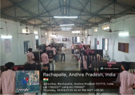
ELECTRICAL MACHINES LAB
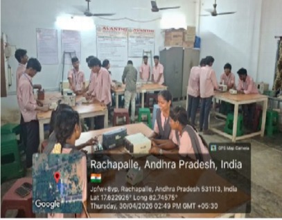
ELECTRICAL CIRCUITS LAB
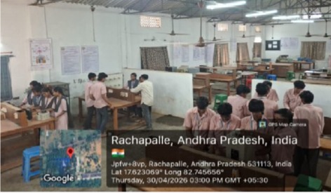
CONTROL SYSTEMS LAB
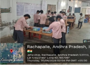
POWER ELECTRONICS LAB
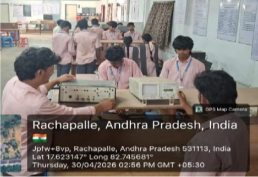
ELECTRICAL MEASUREMENTS LAB
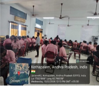
COMPUTER LAB
Additional Lab Facilities
| S.No | Name of the Facility | Details | Purpose for creating facility | Utilization | Relevance to POs/PSOs |
|---|---|---|---|---|---|
| 1 | 3-phase full Converter and DC Drive Setup | 3-phase full converter operating on R& RL loads and its application in DC motor drive speed control | To provide practical understanding of controlled rectifiers and their applications in DC motor drives. | 3rd EEE students perform experiments to study converter operation, firing-angle control, output waveforms, and DC motor speed control. | PO1, PO2, PO3, PO4, PO5, PO9, PO11, PSO1, PSO2 |
| 2 | AC Voltage Controller with Motor Load | Three-phase AC voltage controller feeding a three-phase induction motor load for studying voltage control and motor performance. | To provide practical understanding of AC voltage control techniques and their application in controlling the speed and performance of induction motors. | 3rd EEE students perform experiments to study the effect of firing-angle control on output voltage, motor speed, current, and performance characteristics. | PO1, PO2, PO3, PO4, PO5, PO8, PO9, PO11, PSO1, PSO2 |
| 3 | IGBT-Based PWM Inverter Setup (1-Phase & 3-Phase) | 1-phase and 3-phase IGBT-based PWM inverter setup for R and RL load operation, with facilities for PWM generation and waveform analysis. | To provide hands-on knowledge of PWM inverter operation, control techniques and performance analysis for power electronic applications. | 3rd EEE students conduct experiments to generate PWM signals, observe inverter waveforms and analyze the performance of R and RL loads under different operating conditions. | PO1, PO2, PO3, PO4, PO5, PO8, PO9, PO11, PSO1, PSO2 |
| 4 | Microcontroller-Based PWM Pulse Generation Setup | Microcontroller-based PWM pulse generation system for controlling and triggering power electronic switches in converter and inverter applications. | To provide hands-on experience in digital PWM generation, duty-cycle control, switching control and interfacing of power electronic devices using a microcontroller. | 3rd EEE students use the setup to generate and observe PWM pulses, vary duty cycle and switching frequency, implement control logic, and interface the PWM signals with power electronic converters/inverters. | PO1, PO2, PO3, PO4, PO5, PO9, PO11, PSO1, PSO2 |
| 5 | Sequence Impedance of 3-Phase Transformer | Experimental setup for determination of positive-, negative-, and zero-sequence impedances of a three-phase transformer. | To provide hands-on experience in determining sequence impedances of a three-phase transformer and to understand their significance in unbalanced and fault conditions. | 4th EEE students conduct experiments to determine positive-, negative-, and zero-sequence impedances, analyze sequence components, and apply the results to the analysis of unbalanced and fault conditions in power systems. | PO1, PO2, PO3, PO4, PO5, PO11, PSO1, PSO2 |
| 6 | Calibration of Tong Tester | Calibration and verification setup for measuring AC/DC current using a tong tester (clamp meter) against a standard reference instrument. | To provide hands-on experience in calibration, accuracy verification and error determination of current-measuring instruments. | 3rd EEE students perform calibration and verification experiments, compare measured values with reference values, determine measurement errors, and assess the accuracy of the tong tester. | PO1, PO2, PO4, PO5, PO11, PSO2 |
| 7 | ABCD Parameters of Transmission Network | Transmission line model setup for experimental determination of ABCD parameters under different loading conditions. | To determine the transmission (ABCD) parameters of a transmission line and analyze the relationship between sending-end and receiving-end voltage and current. | 4th EEE students perform experiments to determine A, B, C and D parameters, verify the transmission-line equations, and analyze voltage regulation, transmission efficiency, and line performance under different loading conditions. | PO1, PO2, PO3, PO4, PO5, PO11, PSO1, PSO2 |
| 8 | Sequence Impedance of Synchronous Machine by Fault Analysis | To determine the positive, negative, and zero sequence impedances of a synchronous machine under appropriate test/fault conditions. | To determine the sequence impedances of a synchronous machine and analyze its performance under different fault conditions. | 4th EEE students understand symmetrical components, fault analysis, and the behavior of synchronous machines during unbalanced faults. | PO2, PO3, PO4, PSO1 |